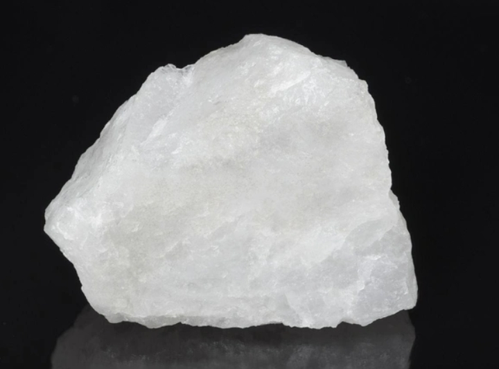
No polymer formulation engineer can bypass silicon dioxide (SiO₂). The strength of silicone rubber, the anti-blocking properties of films, the application feel of adhesives, the reliability of chip packaging — the performance ceiling of many systems is set not by the resin, but by this single dose of filler.
But most people misunderstand it. Do not mistake industrial silica for ordinary sand or glass powder! Ordinary sand is an inert impurity. Specialty silica for polymers is a functional core filler with controllable microstructure. The key to this “controllability” lies in the grinding and forming equipment used during production. Different equipment routes determine the morphology, particle size, surface state, and even the final functional positioning of SiO₂. Used correctly, it becomes the structural backbone of the system. Used incorrectly, it becomes the root cause of agglomeration, white spots, bubbles, and rheological failure — directly ruining an entire formulation batch.
1. Same Silicon Dioxide(SiO₂) Formula, Vastly Different Performance: Production Process and Equipment Make the Difference
The chemical formula is identical. But the production process and core equipment determine morphology, performance, and application scenarios. Three mainstream filler types correspond to three entirely different equipment systems:
01 Fumed Silica (The Structural Champion)
FUMED SILICA
Silicon Tetrachloride (SiCl₄)
▼ Hydrogen-Oxygen Flame Hydrolysis Reactor (1000°C–1600°C)
▼ Fumed SiO₂ Aggregates → Cyclone Collector + Bag Filter
▼ Deacidification Tower (Steam Strips Residual HCl)
▼ Finished Fumed Silica
Core Equipment: The key apparatus in the fumed process is the high-temperature flame hydrolysis reactor. SiCl₄ vapor is fed into a hydrogen-oxygen flame. At 1200–1600°C, it instantly hydrolyzes into smoke-like Silicon Dioxide(SiO₂) nanoparticles. These particles collide and fuse in the flame, forming three-dimensional chain-branched aggregate structures. The particles are then collected by cyclone collectors and bag filters. A deacidification tower uses steam to strip residual hydrogen chloride gas, yielding a pure final product. The entire process involves no mechanical grinding. The microstructure is determined entirely by the thermodynamic and fluid dynamic conditions within the flame reactor.
Equipment Determines Microstructure
The temperature field distribution, gas velocity ratio, and residence time in the flame hydrolysis reactor directly determine the three-dimensional chain-branched morphology and the enormous specific surface area of fumed silica. This fluffy nano-scale structure cannot be achieved through mechanical grinding. It is a “synthesized” morphology, not a “ground” one. Fine-tuning equipment parameters can change the specific surface area (from 100 to 400 m²/g), primary particle size, and aggregate structure. This enables precise control of the final rheological performance.
Microstructure: Three-dimensional chain-branched aggregates, fluffy nano-scale structure, extremely large specific surface area.
Key Features: Extremely fine, lightweight, easily airborne, relatively high unit price.
Positioning: Structure-dominant functional filler, primarily for rheology control.
02 Precipitated Silica (The Cost-Effective Generalist)
PRECIPITATED SILICA
Sodium Silicate (Na₂SiO₃) + Acid Solution (H₂SO₄/HCl)
▼ Reaction Vessel (Stirring, Temperature Control, pH Control) → Precipitation Forms SiO₂ Gel
▼ Filter Press (Washing) → Drying Equipment (Spray Dryer / Rotary Dryer)
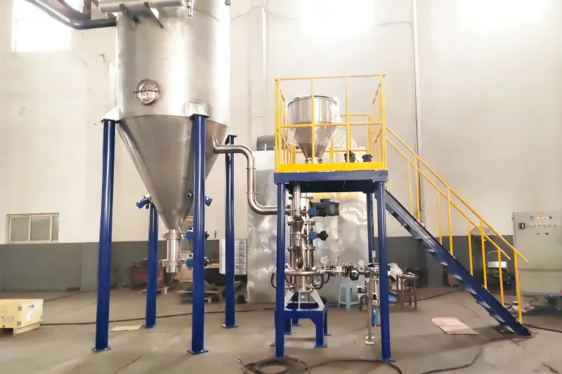
▼ Jet Mill / Vibration Mill (Deagglomeration)
▼ Fine Powder Classifier → Finished Precipitated Silica
Core Equipment: The heart of the precipitation process is the reaction vessel. Sodium silicate and acid react in aqueous solution. By precisely controlling the stirring speed, temperature, pH value, and feed rate inside the reactor, Silicon Dioxide(SiO₂) precipitates out. The reaction conditions determine the initial particle morphology and pore structure. The slurry then passes through a filter press for washing. This removes by-products such as sodium sulfate. Next, it enters drying equipment — commonly a spray drying tower or rotary dryer. The dried powder often forms hard agglomerated lumps. These must be broken apart using a jet mill or vibration mill. A fine powder classifier then screens the material to the target particle size. Only then is it suitable for downstream applications.
Equipment Determines Product Tunability
The reaction vessel parameters (temperature, pH, stirring shear rate) are the root of precipitated silica’s tunability. Different parameter combinations yield products ranging from rubber-reinforcement grades to film anti-blocking grades. The choice of deagglomeration equipment after drying is equally critical. Jet mills use high-speed air collisions to pulverize. They introduce no media contamination, making them ideal for high-purity requirements. Vibration mills use high-frequency vibrating grinding media to break up agglomerates. They offer higher capacity and lower cost, making them suitable for large-scale general-purpose production.
Microstructure: Granular agglomerates, excellent specific surface area, higher moisture content.
Key Features: Low cost, strong tunability, wide applicability.
Positioning: Cost-effectiveness-driven reinforcing filler, primarily for rubber reinforcement and film anti-blocking.
03 Spherical Fused Silica (The High-End Precision Specialist)
SPHERICAL FUSED SILICA
High-Purity Quartz Powder (Pre-stage: Ball Mill / Jet Mill + Classifier)
▼ High-Temperature Flame Spheroidization Furnace (Oxygen-Acetylene / H₂-O₂ Flame, 2000°C+)
▼ Micro-Powder Atomizing Feeder → Powder Melts in Flame, Surface Tension Forms Spheres
▼ Quench Chamber (Rapid Cooling Sets Shape) → Cyclone Collection + Bag Filter
▼ Classification & Screening → Finished Spherical Silica
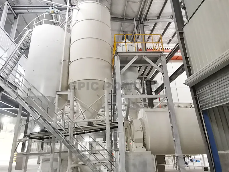
Core Equipment: Spherical silica production is the most complex stage in the grinding equipment system. It consists of two phases: “pre-stage grinding” and “spheroidization.” In the pre-stage, high-purity quartz is ground to micron size using a ball mill or jet mill. A fine powder classifier selects angular particles of the correct size as feedstock for spheroidization. The core equipment for the spheroidization phase is the high-temperature flame spheroidization furnace. It uses an oxygen-acetylene or hydrogen-oxygen flame to produce temperatures above 2000°C. A specialized micro-powder atomizing feeder continuously and uniformly injects angular quartz powder into the flame. The powder instantly melts at high temperature. Surface tension causes it to contract into smooth microspheres. The particles then enter a quench chamber for rapid cooling and shape setting. Finally, a cyclone collector and bag filter collect the finished product.
Equipment Determines Sphericity and Yield
Three factors determine sphericity and yield: the flame temperature field design, the atomization uniformity of the feeder, and the quench rate. Feeder stability is especially critical. Ultrafine powders agglomerate easily and flow poorly. Traditional feeders struggle to achieve uniform delivery. Breaking through this bottleneck requires redesigning the powder hopper structure and feed pickup mechanism. Additionally, the particle size control from the pre-stage ball mill or jet mill directly determines the post-spheroidization particle size distribution. If the pre-stage particle size is uneven, larger particles will not fully spheroidize during their brief residence in the flame. This produces irregular defective particles and directly reduces the yield of high-end packaging-grade products.
Beyond the flame fusion method, other equipment routes exist. The plasma method uses a high-temperature plasma arc to melt powder. The electric heating fusion method employs an electrically heated melting furnace, atomization unit, and quench chamber. The mechanical shaping method uses high-speed impact mills and media stirred mills to apply continuous mechanical force to angular silica powder. This blunts the edges and improves roundness. Each route represents a trade-off between cost and quality.
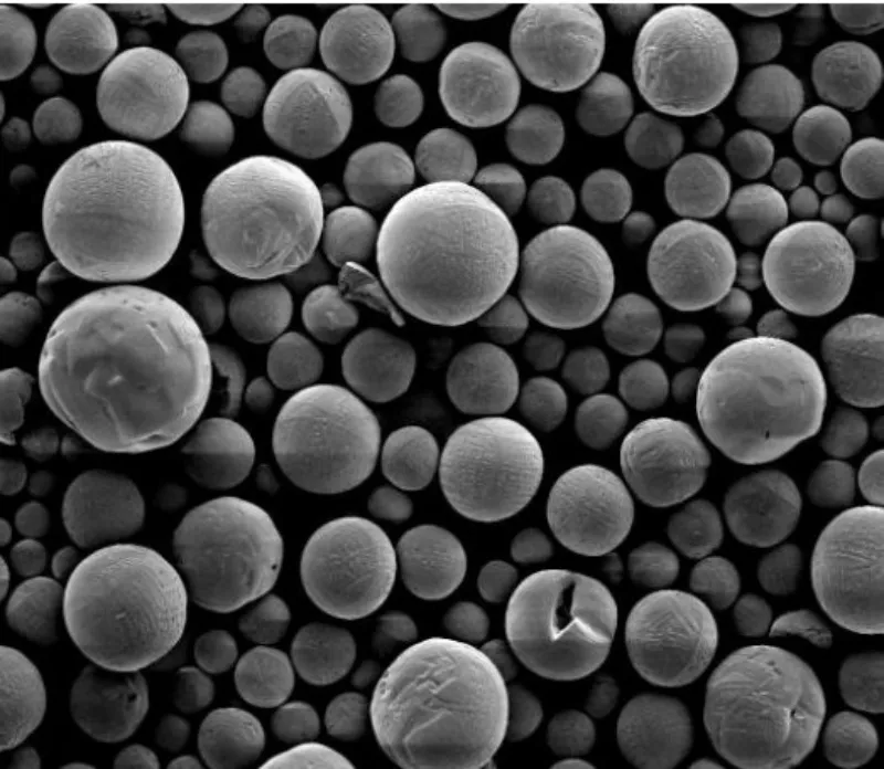
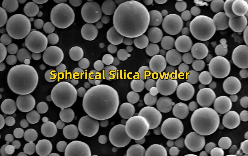
Microstructure: Micron/sub-micron regular spheres, smooth surface with no sharp edges.
Key Features: Excellent flowability, extremely low coefficient of thermal expansion (CTE), superior insulation.
Positioning: Morphology-driven high-end filler, dedicated to semiconductor packaging.
2. Three Core Application Mechanisms and Equipment Synergy
Silica is never a passively filled inert powder. It is an active variable that changes the rheological, mechanical, and thermal properties of the system. Grinding and surface treatment equipment provide the process assurance needed for these functions to perform reliably.
✅ Fumed Silica: Mastering Thixotropy for Rheology and Workability
Application Scenarios: Silicone sealants, epoxy adhesives, industrial coatings. Its surface is rich in silanol groups (-OH). These can bond with each other in a resin system, forming a stable, reversible hydrogen-bond network.
- At Rest: The hydrogen-bond network forms. System viscosity spikes. This provides perfect anti-sagging and anti-settling performance.
- Under Shear (Application): The hydrogen-bond network breaks. Viscosity drops rapidly. Brushing, dispensing, and troweling become smoother.
This is the thixotropy essential to high-end adhesives. It relies entirely on the precise control of fumed silica. The source of this control lies in the parameters of the flame hydrolysis reactor. The specific surface area and the density of the aggregate structure directly determine the strength of the hydrogen-bond network and the thixotropic performance.
Equipment Synergy: Hydrophobic Modification Unit
When reinforcement is needed but thickening is not, fumed silica must undergo hydrophobic modification. Hydrophilic fumed silica is fed into a hydrophobic treatment unit. Under nitrogen protection, dimethyldichlorosilane (DMDC) is pumped in. The reaction proceeds at 300–500°C for 3 hours. Surface methyl groups cover the silica, blocking hydrogen-bond formation. After modification, steam deacidification removes residual by-products. The result is a low-thickening, high-reinforcing hydrophobic fumed silica. The temperature control precision and reaction uniformity of this unit directly determine the modification effect and batch-to-batch stability.
✅ Precipitated Silica: Reinforcement and Toughening for Film Blocking and Tire Energy Loss
Scenario 1: Green Tire Reinforcement. Precipitated silica replaces traditional carbon black. Used with silane coupling agents, it forms strong physical and chemical bonds with rubber molecular chains. This significantly reduces rolling resistance and fuel consumption. It also improves tire grip and wear resistance.
Scenario 2: BOPET/BOPP Film Anti-Blocking. Film surfaces that are too smooth tend to stick together during winding. Adding precipitated silica creates uniform micro-protrusions on the film surface. This reduces the contact area between film layers. It precisely solves the industry pain point of film blocking and difficult separation.
Equipment Synergy: Reactor Tuning + Drying/Deagglomeration System
Tire-grade and film anti-blocking precipitated silica have entirely different performance requirements. Yet they come from the same type of reaction vessel. The difference lies in reaction temperature, pH curve, and stirring shear rate. Tire-reinforcement grades require higher structure (high DBP oil absorption value). The reactor must maintain higher reaction concentration and a specific stirring pattern. Film anti-blocking grades require a narrower particle size distribution and more uniform particle morphology. The reaction conditions are milder. The deagglomeration step after drying is equally critical. Jet mills can precisely deagglomerate to the target particle size without damaging the original particle structure. The classifier ensures uniform particle size. If particle size is uneven, coarse particles in precipitated silica added to films can puncture the film and cause defects.
✅ Spherical Fused Silica: Stabilizing Pressure, Controlling Expansion, and Protecting Chip Cores
Application Scenarios: Epoxy molding compounds (EMC), copper-clad laminates (CCL), and other semiconductor packaging materials. In chip packaging compounds, spherical silica can account for 70%–90% of the formulation. It is the undisputed core filler.
Epoxy resin has a very high coefficient of thermal expansion. When the chip heats up during operation, the resin expands. This expansion can easily tear ultra-fine gold wires and damage the chip. Spherical fused silica offers ultra-low CTE, high insulation, and high flowability. It powerfully suppresses the overall thermal expansion of the system. Meanwhile, the smooth spherical structure prevents flow blockage. Even at high filler loadings, it maintains processability.
Equipment Synergy: Pre-Stage Grinding Precision Determines Packaging Reliability
The quality of spherical silica is determined as early as the pre-stage ball mill or jet mill particle size control. If the pre-stage particle size distribution is too wide, the flame fusion process will produce large numbers of non-spherical and irregular particles. These irregular particles reduce flowability and create stress concentration points in high-loading packaging compounds. This directly threatens chip packaging reliability. Industry leaders prefer jet mills (fluidized bed jet milling technology with integrated classification) for the pre-stage. The grinding process generates no temperature rise. Wear is minimal. There is no media contamination. This makes it ideal for ultra-pure, ultra-fine grinding of high-purity materials. The D97 can be controlled between 2–60 μm. This provides precisely sized feedstock for the subsequent spheroidization step.
3. Solutions: Process Synergy Between Grinding Equipment and Surface Modification
The core of SiO₂ application is never simply “buy powder, add it in.” It is surface modification + process matching. Feeding untreated powder directly will most likely result in defective scrap! Every step of surface modification and downstream dispersion relies on corresponding equipment.
❌ Poor Dispersion: Frequent White Spots and Agglomeration
Symptom: After mixing, the compound is covered with white lumps. The product cross-section shows distinct white spots. Mechanical properties are uneven.
Root Cause: Silicon Dioxide(SiO₂) surface hydroxyl groups are extremely active. The hydrogen-bonding force between particles is strong. Ordinary mixing cannot break up the agglomerates.
Solution: High-Shear Equipment + Silane Coupling Agent Modification
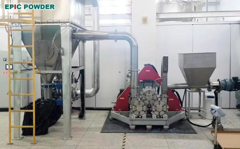
Downstream dispersion requires three-roll mills, planetary mixers, or twin-screw high-shear equipment. These mechanically force deagglomeration and break up agglomerates. Three-roll mills use the speed differential between rollers to generate strong shear. This uniformly disperses fumed or precipitated silica into the resin matrix. Twin-screw extruders achieve continuous dispersion through high-shear zones in the screw elements. On the powder side, a continuous powder surface coating modification system (three-roll modifier) applies silane coupling agents (such as KH550, Si-69) to coat the SiO₂ surface. This improves interfacial compatibility between the powder and resin. The system is based on German technology principles. It accommodates both solid and liquid modifiers. It enables continuous production with high modification uniformity.
❌ Moisture Absorption: Frequent Extrusion Bubbles and Voids
Symptom: During modified plastics extrusion, the strand foams and breaks. The product interior is riddled with micro-voids. Performance drops by half.
Root Cause: Precipitated silica is highly hygroscopic. It readily absorbs moisture during storage and feeding. At high processing temperatures, the water vaporizes and creates defects.
Solution: Pre-Drying + Twin-Screw Vacuum Venting
Before processing, the powder must be thoroughly dried at 120°C or above for several hours. This is done in a dryer or hot-air circulating oven. It completely removes adsorbed moisture. During extrusion, the vacuum venting section of the twin-screw extruder is strengthened. A vacuum port is set at a specific position on the barrel. High vacuum extracts residual water vapor released from the material in its molten state. This prevents bubbles from remaining in the product. For batches of precipitated silica with very high moisture content, dual-stage venting (two venting sections in series) may be needed. This ensures thorough moisture removal.
❌ Rheological Failure: Viscosity Spikes with Minimal Addition
Symptom: A small amount of fumed silica causes the system to instantly thicken. Mixing becomes difficult. Equipment load exceeds limits.
Root Cause: Hydrophilic fumed silica was used by mistake. It excessively builds hydrogen-bond networks, causing a sudden viscosity spike.
Solution: Hydrophobic Modified Fumed Silica — Controlling Hydrogen Bonds at the Source
When reinforcement is needed but thickening is not, prioritize hydrophobic fumed silica. After synthesis, the fumed silica is processed through a dedicated hydrophobic modification unit. Under nitrogen protection, dimethyldichlorosilane is introduced. The reaction at 300–500°C covers the surface with methyl groups. This blocks hydrogen-bond formation between silanol groups. The modified hydrophobic fumed silica provides low thickening and high reinforcement in the system. The addition amount can be significantly increased without triggering a viscosity surge. The key to this modification equipment lies in reaction temperature field uniformity and precise dosing of the silane. Excessive silane makes the powder overly hydrophobic, reducing compatibility with resin. Insufficient silane fails to fully block hydrogen bonds.
4. Full Equipment Overview: The Equipment Matrix from Synthesis to Application
| Silicon Dioxide(SiO₂) Type | Core Production Equipment | Key Grinding / Modification Equipment | Downstream Dispersion Equipment |
|---|---|---|---|
| Fumed Silica | H₂-O₂ Flame Hydrolysis Reactor, Cyclone Collector, Bag Filter, Deacidification Tower | Hydrophobic Modification Unit (DMDC High-Temp Reactor, 300–500°C) | Three-Roll Mill, Planetary Mixer |
| Precipitated Silica | Reaction Vessel (Temp/pH Control + Stirring), Filter Press, Spray Dryer | Jet Mill / Vibration Mill (Deagglomeration), Fine Powder Classifier | Twin-Screw Extruder (High-Shear Dispersion) |
| Spherical Fused Silica | High-Temp Flame Spheroidization Furnace, Micro-Powder Atomizing Feeder, Quench Chamber | Pre-stage: Ball Mill / Jet Mill + Classifier; Post-stage: Classification & Screening | High-Speed Mixer, Twin-Screw Extruder |
| Angular Silica Flour (Basic Grade) | — | Ball Mill, Vibration Mill, Jet Mill, Fine Powder Classifier | High-Speed Mixer |
5. Conclusion: Equipment Is Function, Process Is Performance
Looking at the transformation of silica from ore to functional filler, one fact becomes clear: the performance ceiling of SiO₂ is set not by the chemical formula, but by the equipment route. The same three characters “SiO₂,” when processed through a flame hydrolysis reactor, become the fluffy nano-scale champion of rheology control. When processed through a reaction vessel and jet mill, they become the cost-effective reinforcing generalist. When processed through a ball mill and flame spheroidization furnace, they become the high-end precision spherical silica that protects chip safety.
At the downstream application stage, the synergy between surface modification equipment (three-roll modifiers, hydrophobic treatment units) and high-shear dispersion equipment (three-roll mills, twin-screw extruders) provides the final process safeguard. It transforms powder from “purchased raw material” into “well-applied functional filler.” Poor dispersion, moisture-induced bubbling, and rheological failure — the pitfalls that formulators frequently encounter — often stem not from the powder itself. The root cause lies in inadequate equipment selection and process matching.
Understand the fundamental logic that “equipment is function, process is performance.” Only then can you truly: select the right powder, use the right equipment, and formulate the right recipe. This lets silica return from “the root of all evils” to its rightful place as the “universal filler.”

“Thanks for reading. I hope my article helps. Please leave a comment down below. You may also contact Zelda online customer representative for any further inquiries.”
— Posted by Emily Chen